
首页 论坛 原厂专区 NXP(freescale) MCU AN2295 bootloader文档解析(三)


 楼主
楼主
运行平台
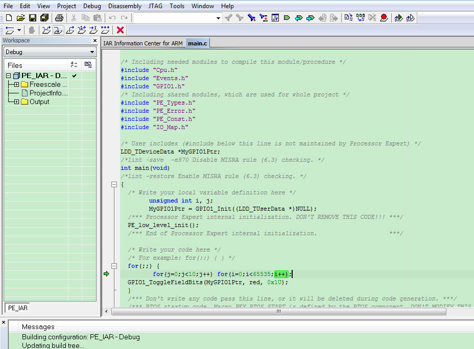
运行例程(IAR)


运行例程。
1. Boot loader上位机使用手册
Ø 修改User code工程的linker file文件(以IAR ICF file为例)
Ø 生成S19文件设置
/*###ICF### Section handled by ICF editor, don't touch! ****/
/*-Editor annotation file-*/
/* IcfEditorFile="$TOOLKIT_DIR$\config\ide\IcfEditor\cortex_v1_0.xml" */
/*-Memory Regions-*/
//define symbol __ICFEDIT_region_ROM_start__ = 0; //修改前
define symbol __ICFEDIT_region_ROM_start__ = 0x00001000; //修改后
define symbol __ICFEDIT_region_ROM_end__ = (64*1024) -1;//********
define symbol __ICFEDIT_region_RAM_end__ = 0x20000000;
define symbol __ICFEDIT_region_RAM_start__ =__ICFEDIT_region_RAM_end__ - (4*1024)/4 + 0x410;//********
define symbol __region_EEPROM_start__ = 0x10003100;
define symbol __region_EEPROM_end__ = __region_EEPROM_start__ -1 + 256; // 256 bytes
/*-Specials-*/
define symbol __ICFEDIT_intvec_start__ = __ICFEDIT_region_ROM_start__;
/*-Sizes-*/
define symbol __ICFEDIT_size_cstack__ = (1*1024);//********
define symbol __ICFEDIT_size_heap__ = (1*1024);//********
/**** End of ICF editor section. ###ICF###*/
define symbol __region_RAM2_start__ = 0x20000000;
define symbol __region_RAM2_end__ = __region_RAM2_start__ + ((4*1024)*3)/4;//********
//define exported symbol __VECTOR_TABLE = 0x00000000; //修改前
define exported symbol __VECTOR_TABLE = 0x00001000; //修改后
define exported symbol __VECTOR_RAM = __ICFEDIT_region_RAM_start__ - 0x410;
define exported symbol __BOOT_STACK_ADDRESS = __region_RAM2_end__ - 8;
define symbol __code_start__ = __ICFEDIT_region_ROM_start__ + 0x410;//********
define memory mem with size = 4G;
define region ROM_region = mem:[from __ICFEDIT_region_ROM_start__ to __ICFEDIT_region_ROM_end__] | mem:[from __region_EEPROM_start__ to __region_EEPROM_end__];//********
define region RAM_region = mem:[from __ICFEDIT_region_RAM_start__ to __region_RAM2_end__] | mem:[from __region_RAM2_start__ to __region_RAM2_end__];
define block CSTACK with alignment = 8, size = __ICFEDIT_size_cstack__ { };
define block HEAP with alignment = 8, size = __ICFEDIT_size_heap__ { };
initialize manually { readwrite };
initialize manually { section .data};
initialize manually { section .textrw };
do not initialize { section .noinit };
define block CodeRelocate { section .textrw_init };
define block CodeRelocateRam { section .textrw };
place at address mem:__ICFEDIT_intvec_start__ { readonly section .intvec };
place at address mem:__code_start__ { readonly section .noinit };
place in ROM_region { readonly, block CodeRelocate};
place in RAM_region { readwrite, block CodeRelocateRam,
block CSTACK, block HEAP };
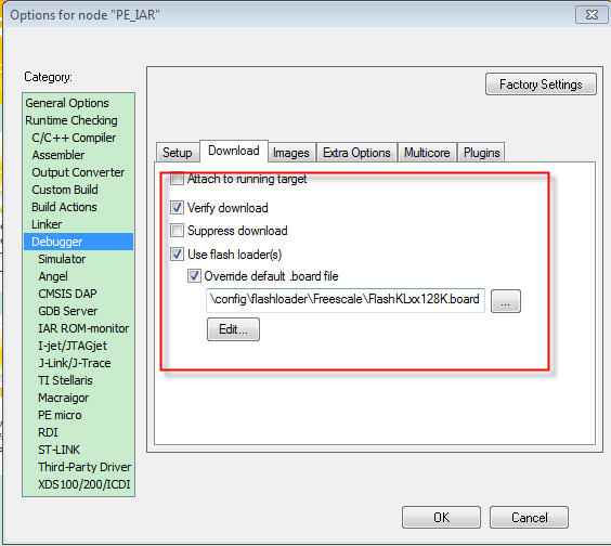
l 选中工程后,右击后并单击【Options】,图2所示;

l 勾选【Generate additional output】,并选择【Motorola】作为Output format,如图3所示;


1) 上位机与FRDM-KE02建立连接

Ø 【1】:选择合适的COM;
Ø 【2】 : 选择协定好的波特率;
Ø 【3】:选择User code工程生成的S19文件;
Ø 【4】:点击Connect,接着复位Target,使得Boot loader例程重新运行。
4) User code更新
经上述3步骤后,上位机的Identification框中会显示Boot loader的相关属性信息(如图6所示),同时主窗口还显示了MCU的封装形式、Flash特性、中断向量表重定向地址、User code所占Flash空间等信息,表明了上位机与Target连接建立成功,接着点击【Program】,即可实现User code更新,如图7所示。


 回复
回复
 举报
举报

块
导
航
举报
请选择举报类别
- 广告垃圾
- 违规内容
- 恶意灌水
- 重复发帖
